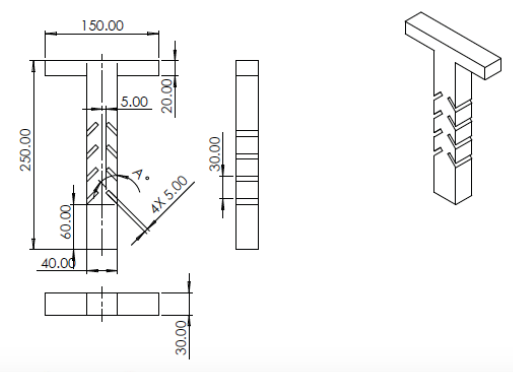
GOAL The goal of this project was to become familiar with existing research related to microfluidic mixing, and to design and simulate a novel microfluidic mixer design based on those findings. BACKGROUND Microfluidic mixing is, by definition, mixing of two or more fluids at microscale. Such ‘miniaturization’ of fluid mixing components implies decreased sample size requirements, increased speed of sample processing, and reduced manufacturing cost, all of which are desirable in conducting chemical, biological and biomedical research. DESIGN A T-shaped passive microfluidic mixer design was selected due to the shape’s relative simplicity. To establish a control model for this project, a straight-channeled microchannel was designed following the geometric proportions found in previous literature, and scaled to fit the project parameters, listed in the table below. Parameter Value Microchannel width (µm) 40 Inlet width (µm) 20 Microchannel depth (µm) 30 Feature min. size (µm) 5 Overall max. chip size (mm) 20 x 20 To maintain similarity to the control design, as well as to significantly reduce the final length of the microchannel, meander designs were avoided. Baffles were selected over the use of free-standing packing (which causes stream splitting). Straight-channeled Control (Dimensions given in µm) Channel with Mixing Chambers set at Angle A (Dimensions given in µm) Formation of distinct ‘mixing chambers’ by symmetrically placed baffles has been shown to improve mixing efficiency. This design combines more typical rectangular chambers and “fish-shaped” pocket chambers proposed in earlier publications with the aim of both improving mixing efficiency (as measured by mixing index, MI=1-sigma) and reducing manufacturing costs associated with more complex channel geometry. Note: COMSOL SIMULATION The dilution of an aqueous food dye solution with DI water was simulated by modeling fluid flow channels using SolidWorks CAD and COMSOL 6.0, followed by data processing in MATLAB. A COMSOL-generated velocity profile of the mixer is shown (RIGHT). Flow through mixing channels was assumed Laminar (Re <2000), and single phase, as solution and diluent are miscible. Hydraulic diameter, Dh (calculated using perimeter and cross-sectional area of the channel), and diffusivity, D, were used to calculate Peclet numbers for both the straight channel and channels with mixing chambers. Fluid Properties: Sigma vs Channel Length for Control (Top) and Mixer (Bottom) Sigma was calculated from the COMSOL concentration profiles. As expected, there is a larger decrease of sigma with respect to channel length for the channel with baffles than for the straight channel, indicating decreased mixing length. This improved mixing over the straight channel is observed at all Pe (adjusted by inlet velocities) tested. Peclet was also calculated and plotted for this single microchannel against its length. As Pe increases, mixing length appears to rapidly increase as well, then level off after around Pe=100, indicating a low Re, high Pe mixing limit.